
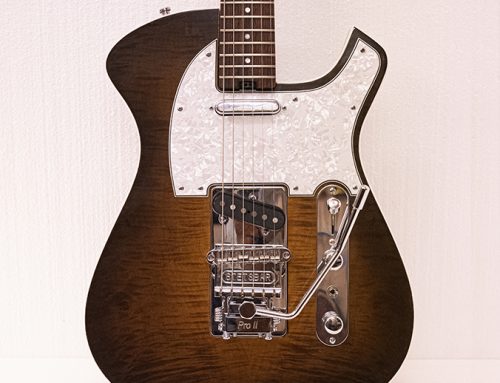
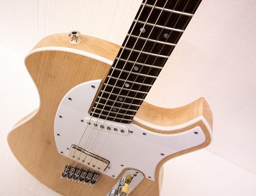
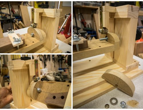
Finally, I finished the plan for the Neck Router Jig! A flexible tool that helps you to create/re-create your favorite necks, or to do more advanced asymmetric neck shapes that otherwise can be time-consuming.
About two years ago I finished the Neck Router Jig and did a post in Swedish about the idea and how it works. And over the past years, I got some request on a plan for this jig. But I had a little resistance to do it because I know it’s a lot of cumbersome work and to relearn the SketchUp tool again. But I did know that I had to do it sooner or later 😉
NOTICE! The measurements on the plans for the Neck Router Jig is based for common guitar scales (appr. 24-27″). So if you want to use it for scales above 27″ you need probably to increase the length on the frames as the router board. The rest as the e.g. “Profile Tracker” will be the same sizes.
Also, check out my previous post this year about the Profile templates. These are the templates I used for this jig.
Download PDF file: NeckRouterJigV1.1
For better resolution: Save the PDF-file to the desktop and open it with Adobe Acrobat Reader.
Get Adobe Acrobat Reader here!
Download Google Sketchup file (*.skp): NeckRouterJigV.1.1
Get the Google Sketchup viewer here!
Hope this plan will help or inspire you to do better necks. Cheers!


![]()
![]()


![]()
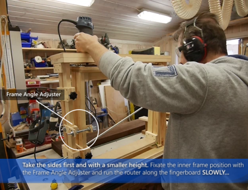
And here’s the jig in action: Neck Shape Jig video

Happy New Year to you, Michael. Thank you for posting these plans. I‘ve been looking at the pictures of this jig during the past few days, planning to finally build one. Therefore, the plans are very welcome, and incredibly generous of you to make them available. Best wishes, Johann.
Thanks!!! Happy New Year to you to! And good luck with the jig! 🙂
Dear Michael
Thank you so much for the plans of this Jig. 🙂 You’re great. I’m a total beginner in guitar building. Best wishes, Mare.
Thanks, Mare! 🙂
Hi Michael, thanks for sharing your great work. What I did not get, where should the location of the axis above the board should be drilled? is it where the fretboard meets the neck or higher? Also, do you think that the location and size of the puck followers matter (besides being on the same level overall). Thanks and best wishes, Chris
Hi Christian! Thanks for the notice! Realize that I have missed specifying that one.
The axis location represents the center where the fretboard meets the neck wood. The measurements on the axis are 8 mm from the bottom of the board and it’s the same on the puck.
Regarding the location: The puck profiles are based on the 1st & 13th fret. So it’s kind of relative in how exactly it replicates. It depends on the distance between the puck & the cuts as how much the puck is enlarged in percent. I’ll guess if you want to be more exact, you have to go into deeper mathematical exercises. 😉 It’s doable… but I’m too lazy for that (for now).
Regarding the puck sizes: Yes matters! I found that 200% enlargement worked best with router distance etc. Using smaller sizes will make every router movements more sensitive. Using bigger sizes will probably make the spring tension harder to operate with as you need longer router bits.
Hope this info gave some answers. Good luck and happy building! BR/ Michael
Sorry! I need to correct myself regarding the axis location
(it was a little bit sloppy answer from me) 😉
It doesn’t represent the center where the fretboard meets the neck wood as I say in the previous comment. Because that will be different each time depending on what fretboard height as what radius you have.
Preferably it should be at the same height where the 1st fret neck edges are. I used 2mm as axis reference on the “Neck Shape Templates for Router Jigs” http://www.kappi.com/blog/wp-content/uploads/Neck-shape-templates-for-Router-Jig-ALL.pdf. The axis on the puck template is 2mm(200%), that represents 1mm on the board. Example; if you are using a 4mm fretboard…
Subtract the radius difference from the fretboard edge ≅2,8-3mm. Divide the number with 2 to get the axis position on the board ≅1-1,5mm and multiply with 2 to get axis position on the puck template.
Anyway, depending on the fretboard height and radius you need to measure and adjust the axis positioning for both templates as the board on every neck work (if they’re not having the same spec of course).
BR/Michael
Hi, how do you spare the progressive asymmetrical profile? Do you cut until the 6 fret, stop and change the template?
Hi Michael! No, I only used the 1st and 13th puck for this jig. This works on both progressive asymmetric shapes as standard neck shapes. (As long as you want a straight line from 1st to 13th fret). The template that I used for the 6th fret on asymmetrical profiles is ONLY for measurement’s sake. Because the line on the 6th fret should be close to or exact to the center.
And when it comes to the neck thickness concept I used a straight line from 20mm(1st fret) to 23mm(6th fret). So it’s no need to change the template.
See the post on Asymmetric neck shapes: http://www.kappi.com/blog/2012/10/asymmetric-neck-shapes/.
And the PDF-file on measurements: http://www.kappi.com/blog/wp-content/uploads/Neck-profile-asymmetric-shape-measurements.pdf
But if you want different thickness or a sloped thickness profile near the end of the neck, You probably need to change template somewhere before the 10th fret I’ll guess.
Hope this gave some answers.
BR
Michael
Thank you so much. I build acoustics as a hobby and want to alter the clamping system to accommodate the angled head stock. As a player that plays a lot of barre chords I notice my thumb position moves as I move up the neck. which profile might you choose for that? I also have a lot of Martin guitar company neck profile measurements if you would like a copy. I would be happy to send them.
Then I would try out the progressive asymmetric neck shape. Because that was the purpose of it when it comes to supporting a better hand grip.
But, I’ll guess that the puck profiles need to be adjusted for acoustic neck standards first. The 1st and the 9th fret puck needs to a little bit higher and wider etc. Do a test first to see if it works for you, 🙂
Please! Send me a copy of the Martin profiles if you have them available. I would love to do an asymmetric profile variant based on these measurements and upload them here. If that’s ok with you of course.
BR/Michael
Hi Michael.
I have a question regarding the templates used to help with the profiling. Do you know where I can find accurate 1:1 templates to copy for the profiles, or do yours work to? And also, do you have any profiles for V shapes, D shape, and U shape? As I saw that you use the C shape more often.
Hi Josiah!
Templates of the 1:1 profiles are here; https://www.kappi.com/blog/2018/06/neck-shape-metrics-templates/
Be sure to uncheck the “fit to page” button before printing. Measure the printout that its the correct size. Have notice that this can be a bug on some browsers reading pdf-files or in the acrobat reader app itselt. If the measurements is not correct… Increase printout size with procentage.(usually ends up around 103% something).
Reg. V-, D- and U-shapes… No.
Hi Michael,
Thanks for publishing your design!
May I ask why the width positions of the profile trackers are adjustable, even in a fairly wide range? I would rather understand some hight adjustment to better accommodate different puck scales.
Best regards
Soenke
Hi Sönke!
The reason to have adjustable positions on the profile templates is that you can adjust the center(appr. band 6) to what-ever neck scale you want to use (also, if you have necks with long heads).
Other reasons are that you can actually have several profile templates installed. In that way you can use them as pair or, if you want to be more experimental… select different profiles at each end. Then, of course you need to adjust the profile trackers and recenter the neck position on the neck frame.
BR/
Michael Käppi
Many thanks for your swift reply and a happy 2020 to you!
Cheers Sönke
(Not necessarily for publishing, up to you:-)
Hi Michael great job. Do you sell these plans? And how much are they. Thanks
Hi Joe! Thanks!
They are free for private use (Creative Commons). 🙂
BR/
Michael
In a sense simple but very functional project!
I have a question, I got a personal idea but I would like to know how you do it.
How do you get the profile of the two silhouettes of the Neck Profile Templates? It should be borne in mind that the copiers are at a distance beyond the normal development of the handle and that they are at 200% of their actual size. You draw them as if the handle continues to that point I guess (enlarged) …
In short, what procedure do you use?
Thank you !
Hi Paolo!
Thanks! 🙂 It’s based on an ordinary C-profile. Read my previous post on progressive asymmetric neck shapes. It was drawn in Illustrator not only for scalability reasons, but also the convenience of using vector-based anchor points to re-balance the proportions of the profile curves.
The second question I’ll guess is about; “Why do I enlarge the profiles by 200%?”
If you have 100% you can’t turn the neck frame at all. Practically, it will be resting on the router board. So you need to be able to turn the neck frame 90 degrees. 180-200% enlargement on profiles is good enough for both turning 90 degrees as distance for the router bit to work properly. Too much enlargement on the profiles will need longer router bits. Hope this answers your questions.
BR/
Michael
Hi Michael, thank you for the speed of your response! Your answer confirms to me that I had correctly understood the question concerning the 200% scale factor and its reasons. I had already viewed your article on progressive asymmetric neck shapes (as well as every page of your precious site) and I must say that I find the theory plausible! Rather I wanted to deepen the method you use to draw the shapes that are placed beyond the beginning and end of the handle … So it is obvious that, in addition to the magnification factor, these should be calculated as a projection of the lines of the handle up to the distance to which they must be placed, as if the handle should continue following the same hypothetical curvature up to that point. I don’t know Illustrator (I’m going to see it), with this software it is therefore possible to recalculate and rescale the shape starting from the real shapes at the neck and body as if they were 2 projections of extension up to the point of attachment of the guide shapes? Obviously the shape to the body will go bigger while the opposite one will go narrower (+ the zoom factor at 200% obviously). I know it’s a commitment but for completeness it would be really interesting to have a short guide about it.
Really thank you for the availability and courtesy. I find your works and your ideas really interesting and intelligent! I have a great passion …
But perhaps, more simply and without too many software tools, proceed simply by rescaling the image according to a percentage factor? For example:
if we had a 1 meter long handle for simplicity (between the 1st and the last fret) and if the guide shapes were positioned 20cm before and after would it mean the following?
The shape towards the body increased to 220% (200% standard enlargement + 20% because 20 centimeters correspond to 20% of the length of the handle for this example)
and the one towards the headstock at 180% (200% – 20% because on this side it goes down)? I would do so on my intuition.
In practice, 2 mathematical formulas and a software that starting from the real shapes would be able to rescale in percentage would be enough. (as well as Photoshop)
Forget it !!!! The formula is wrong! The trend does not follow this rule and linearity! I pronounced myself with intuition without really thinking about it.
FORGET THE HEAVENESS OF MY SPEECH.
The correct mathematical relationship should be the following:
Considering the geometric shape consisting of the 2 extreme sides of the handle (points where I start and end the work respectively) and the distance between them I can calculate the value of increase (or decrease on the opposite side) of the side based on the distance at which I will go to position the template like this:
Side increase = [(long side – short side) / distance between the two] * template distance
The calculated value will correspond to the increase (or decrease) of the side considered.
For example if we had:
Long side = 40
Short side = 20
Distance between sides = 100
Distance of the template from the long side = 50
We will get:
(40-20) / 100 * 50 = 10
The side of the large template will be = Long side+Side increase = 40 + 10 = 50
All to be rescaled at 200%
Same calculation as the opposite for the other side but the value obtained from the calculation will be subtracted from the short side to obtain the effective side of the small template.
At this point we could consider evaluating the right side of the sections of the handle, recalculating the length, rescaling the 2D image using a special software and subsequently applying the 200% magnification and thus obtaining the correct template.
Maybe this could be a correct method ?!
Thanks to those who wanted to read up to here. Greetings to all.
Hi Michael,thank you for sharing neck router plans,l am a beginner to building guitars and it will be really helpful for me. l have a question about fingerboard. While shaping the neck, there is no fingerboard glued to the neck blank,right? You glue the fingerboard after shaping the neck. Maybe because of different fret sizes you just use neck blank on a 5mm fingerboard template. l watched the video and l just saw neck blank on fingerboard template but no glued and fretted fingerboard. Thank you for your help.
Hi Bulent & thanks!
Yes, I glued the fingerboard after the neck shaping. And you can also see that I’ve a piece of wood to compensate the height of the fingerboard. That’s because the fingerboard height are included on the profiles that I’m using.
BR
Michael
Thank you Michael for your answer. Can you also tell me what kind of router bit you use.(maybe also a picture of it too if it is possible)
Thanks for sharing your knowledge… now i find this that allows to copy the complete neck!!!
https://www.youtube.com/watch?v=2UX9w0mAdvY&t=7s Check it out!
WOW!! Really nice!
Thanks for sharing! You could even go for a cooffe break 😉
Hi Michael, I’m building your Jig. Thanks for sharing that nice piece of work.
I didn’t quite understand how to figure out the location of the board axis depending on the fingerboard thickness.
I have read your answer in he first comments, but still don’t understand it. Any chance you could come back on this explanation ? Best regards.
Hi, Michael. Thank you a lot for sharing this amazing project.
I have been working on it during this days and I would like to share the conclusions and difficulties I have come across.
The jig works great but I am struggling with the geometry involved and the shape of the template. I have found that taking the actual shape I want and simply scaling it to 200% doesn’t work fine for me because the router bit goes to deep in the depth side. Let me explain:
If we want a 42 mm neck we must build a 84 mm wide template, right? The actual neck spans half that measure so the router bit should go half the distance between the template end and the center of the axis. That is: 42 mm from the template bound to the axis, so the router bit should be 21 mm from the template bound.
Now let’s move to the depth side and we want say 18 mm (let’s get the fretboard aside for this consideration) so we build a 36 mm high template, right? (Not taking into account fret board compensation, of course). Well, router bit should go half that distance, that is 18 mm from the template bound.
This is the point where things get sticky because the distance of the router bit away from the template bound is fixed. The router bit can be in the middle of the template either in the horizontal position or in the vertical position but never in both.
If I had to say how to design my template I would go the distance of the router from the template (say 21 mm) plus the measure I want in the real neck. Just guessing here…
So my question is: am I missing something o do you use some kind of compensation in your templates?
Thank you indeed for sharing this lovely piece of knowledge, Michael.
Marco
Just finished building your rig. I used metric measurements mostly although some of the material was 1/2″ and 3//4″. Mostly Plywood. Used MDF for the neck base and may reinforce that. It went pretty well and I spent more than a couple of nights figuring out how this thing works and how I was going to make it strong and simple at the same time. Then I realized 1st and 13th fret are about as far as you can go and the also the bottom of the cam moves the router out of the way. Are the cams compensated for the distance between cam and router working area. Also would it be possible to build cams for fretboard shaping? Too cool. Hope you will post more profiles. It’s not as big as I had imagine and will hang nicely on a wall. I may never build another guitar. I saw a more primitive version made and stolen from your site on another feed. Your measurements rock but do not leave much room for error.I still have to mount bearings and add springs. I take it the bearing height is pretty critical.
I plan to also use this machine to cut truss rod grooves. Could be an all in one if it will do progressive fretboard.
Thanks agin. My final build looks like an IKEA. Long live the Sweeds
My Grandmother came from Sweeden as a young girl.
Cal Patterson
Too much fun.
Hi Michael,
Thanks for your generosity! I’m yet to build one but have all the wood ready and will be using a CNC flatbread router to cut it so everything is perfect.
My question for you is, if I want to build a 7 string neck, or a baritone neck or even a bass neck, would I need to build different cradles or even a longer Jig?
Thanks, Kyle
Thank you for posting this. Is there a parts list or cutting layout sheet available?
Hi Odysseyguitar! Thanks! No, thought that the plans was good enough to get started. 😉
Thanks Michael. You are correct, the plan was good enough, I was being lazy. Built one, had to modify it a fair bit because of the angled headstock. Will be trying it out next week. Thanks so much for posting it.
Just stumbled upon your site. Thank you so much for sharing these jig plans. You’re amazing!
Michael, Awesome job on the plans and thank you so much for sharing! It should save me hours with the rasps. I hope to gather materials and build one this weekend!
Now, for the secondary reason for writing you. My grandmother and great aunt were both Swedish and made the best Limpa Bread. Alas, their recipe has been lost to history. I’ve tried a couple “Scandinavian Bakers” in the US, but they never quite get there. Any chance you have a good recipe?
Hi Randy!
Thanks! 🙂
Sorry, I’m not so familiar(lazy) in baking. But I ate a lot of homemade bread growing up.
Certainly taste better and is definitly healthier than the bread you buy. What I remember, there’re not using so much yeast.. I think.
Very good for me. I can finish Necks , trhanks .
Great! 🙂
Hello, This looks like a great tool! Is there a parts list for the hardware? Or maybe I missed it here somewhere?
Sorry! Have no list.
Såg du inte att din halsformande jigg också kan användas för att räta på brädor och du behöver inte göra en separat jigg för det?
Tack för synpunkten!! Japp! Har varit inne på de tankarna och teoretiskt skulle det funka. Men praktiskt så blir vrid-momenten på en 30 cm cirkel-diameter (12 tum ratio greppbräda) otroligt tungt och mer eller mindre omöjlig att hantera, då fjädrarna drastiskt ökar motståndet ju längre du drar mot kanterna. Cirkelrörelsen du får på hals-jiggen är cirka 4 cm gör att vrid-momentet blir enklare att hantera. Men man skulle kunna byta ut delar på halsjiggen som gör horisontala rörelser istället för cirkel-rörelser. Kanske något som jag kan titta på framöver. 😉
Hi Michael!
Many thanks for the gift of these wonderful plans. You are as kind as you are talented.
God bless you.
Damian
Thanks, Damian! 🙂